From visualization to action: Unity, machine information systems, AI agents, and the industrial digital twin
A practical guide for system integrators, OEMs, and automation engineers
In partnership with Thomas Strigl, CEO, realvirtual.io
About the author: Thomas Strigl is CEO of realvirtual.io and has over 18 years of experience in simulation and automation software.
Introduction
In our previous guide, Design, Simulate, Deploy: Why Unity Matters for Industrial Digital Twins, we discussed Unity as a platform for building real-time 3D replicas of industrial systems. The arguments made there continue to apply. In this comprehensive two part e-book series we focus on two topics that increasingly intersect with that foundation:
Rapid development of large language models, AI agents, and the Model Context Protocol (MCP): These have now moved from research contexts to tools that some integrators are beginning to use in production environments.
EU Machinery Regulation (EU) 2023/1230: The regulation was adopted in 2023, and its full application date — 20 January 2027 — is widely known. What is changing now is the proximity of the deadline. What is changing now is the proximity of the deadline. With less than two years remaining, the supporting framework is taking shape: harmonized standards are being revised, the application guide is being drafted, and machine builders are moving from awareness to implementation. New cybersecurity provisions are becoming operational requirements, while the regulation’s explicit support for structured digital documentation is shifting documentation from a static deliverable toward a maintained lifecycle resource.
These two developments are usually discussed separately. This e-book series discusses them together because the underlying work overlaps significantly. AI systems require structured, grounded data. Structured digital documentation prepared for regulatory compliance can also serve as grounding material for industrial AI systems. The four-layer architecture described in Part 1 — signals, MES context, documentation, and spatial context — supports both the operator and any AI tools added later.
The 3D HMI — or, more accurately, the Machine Information System that emerges when live machine data, enterprise context, and structured documentation are integrated into the same spatial surface — is where machine data, documentation, and AI-generated information come together for the operator.
The intention here is not to make claims about AI transforming the factory, but to describe practical architectural patterns that integrators may find useful, using tools and standards that are already available. The architecture stands on its operational value alone; the regulation simply makes the timing more explicit for the European market.
Part 1
The connected layer: Data, documentation, and the 3D HMI
1. Beyond the Digital Twin
The previous e-book discussed digital twins as tools that become more useful when they connect to real automation systems and reflect real machine behavior across the lifecycle. That foundation continues to shape how manufacturers approach digital transformation today.
For system integrators, the value question is usually less about visual fidelity and more about integration. A packaging line, a stacker crane, or a distributed warehouse needs to be operable, supportable, and maintainable — often for ten years or more. The relevant question becomes how well the digital twin connects the data, the people, and the documentation that make the system supportable over its operational life.
The operational benefits of this kind of integrated environment are substantial, and they are independent of any regulatory contex:
- Faster fault diagnosis:
A 3D HMI connected to live machine and process data shortens fault diagnosis time, because the operator can see the affected component in spatial context rather than mapping a symbolic fault code to a physical location.
- Decrease in expertise barrier:
Lowers the experience threshold for new staff, shift workers, and rotating personnel — relevant in nearly every industrial sector given the well-documented shortage of skilled technicians in mechanical and electrical fields.
- Effective remote support:
Makes remote support meaningful, because the manufacturer’s service technician sees what the operator sees, in the same 3D context, and can give precise instructions.
- Training without production disruption:
Allows training to happen against the actual machine configuration without halting production.
- Operational context at the machine level:
Lastly, when machine information system data — orders, batches, KPIs, energy figures — is overlaid on the same 3D view, the operator sees not just whether a machine is running, but how it is performing in context.
These benefits accrue regardless of whether a documentation package is required by regulation. They are the operational case for the architecture this guide describes. The regulatory case, discussed in section 3, runs in parallel: the structural changes the new EU Machinery Regulation introduces happen to align with the same architecture, which means the regulatory work and the operational work overlap rather than competing for separate budgets.
This shifts the role of the digital twin. The 3D model is not only a visualization — it can also serve as a spatial index that ties together signals, enterprise data, and documentation in a form that operators, and increasingly AI tools, can navigate.
2. The four data layers behind a working digital twin
A digital twin used in operation typically interacts with four distinct data layers. Each is incomplete on its own.
The signal layer is the fastest and lowest. PLC inputs and outputs, drive positions, sensor states, alarms — values that change in millisecond cycles. This is the layer that virtual commissioning and behavior simulation already use, typically through OPC UA, Beckhoff ADS, Siemens S7 TCP/IP, or MQTT. For most digital twin use cases an update cycle in the 10–50 ms range is sufficient.
The MES layer is slower and broader. Production orders, batches, recipes, KPIs, material flows, quality records, energy figures. This data is event-driven and is typically accessed through REST APIs, OPC UA, message brokers, or direct database connections. This layer provides the context that makes signal data interpretable: the same conveyor running at the same speed has a different meaning depending on which order it is currently processing.
The documentation layer is the one that has historically received the least attention. Operating instructions, electrical schematics, P&ID diagrams, risk assessments, declarations of conformity, parts lists, software versions, maintenance procedures, service histories. In most installations this layer exists as a binder, a network share, or a PDF archive — searchable only by humans who know what they are looking for. Under the new EU Machinery Regulation, the structure of this layer is changing, which is the subject of the next section.
The spatial/contextual layer is the 3D model itself. It can serve as a unifying coordinate system across the other three layers. A signal address is abstract; the same signal mapped onto a specific valve that an operator can see and click on is more directly interpretable.

Diagram: The Four Layers of a Working Digital Twin — four horizontal bands stacked vertically. From top to bottom: “Spatial / 3D Context (Unity scene, kinematics, component IDs)”, “Documentation (manuals, schematics, declarations, software versions)”, “MES (orders, KPIs, batches, materials)”, “Signal Layer (PLC I/O, drives, sensors, alarms)”. Vertical arrows on the right show information flowing both upward (state) and downward (commands, queries). A small operator/agent icon on the right side accesses all four layers through the spatial context at the top. Diagram courtesy: Realvirtual.io
3. Documentation under the new machinery regulation
For more than a decade, technical documentation accompanying machinery placed on the European market has been governed by the Machinery Directive 2006/42/EC. The familiar obligations — a technical file under Annex VII, instructions for use, an EC Declaration of Conformity, a 10-year retention period — have generally been met through printed manuals, PDF archives, and paper declarations.
This framework is being replaced. Regulation (EU) 2023/1230, the new machinery regulation, was adopted on 14 June 2023 and will come fully into effect on 20 January 2027. It repeals Directive 2006/42/EC and, as a regulation rather than a directive, applies directly across all EU member states without requiring national transposition.
The regulation has been on the books for some time, but the supporting framework is still being completed. The commission’s standardisation request to CEN and CENELEC was adopted in January 2025, with the goal of having a complete set of harmonised standards published in the official journal by the end of 2026. The first drafts of the official application guide are expected from early 2026 onward, with final publication likely toward the end of 2026. The practical interpretation work is happening now, and projects placed on the market from 20 January 2027 onward will need to comply.
Before describing the changes, one crucial point of note, because it is widely misread: paper documentation remains fully compliant under the new regulation. The changes described below apply to manufacturers who choose to deliver documentation digitally — a path the regulation now explicitly opens, but does not mandate.
Three changes introduced by the regulation are particularly relevant for machine builders and system integrators. The relevant articles are reproduced verbatim in the appendix.
Digital documentation is now explicitly permitted: Article 10(7) allows instructions for use to be provided in a digital format. Article 10(8) allows the EU Declaration of Conformity to be provided digitally, accessible via an internet address or machine-readable code. Assembly instructions for partly completed machinery (Article 11) may also be supplied digitally. Paper must still be available on request, and certain safety-critical information for non-professional users must remain on paper.
For manufacturers who choose the digital route, the documentation must remain accessible online for at least 10 years after the machinery is placed on the market, or for the expected lifetime of the machine, whichever is longer. In practice this is rarely just ten years: industrial machines routinely operate for fifteen, twenty, or even thirty years, so the lifetime clause is the binding constraint for most installations rather than the 10-year baseline. The manufacturer remains responsible for keeping the documentation reachable, current, and version-controlled across the lifecycle.
Cybersecurity is added as an essential health and safety requirement. Annex III, in sections 1.1.9 (Protection against corruption) and 1.2.1 (Safety and reliability of control systems), requires control systems to withstand reasonably foreseeable malicious attempts that could lead to a hazardous situation. AI-based safety functions and self-learning systems are explicitly within scope, with stricter conformity assessment for high-risk categories.
The practical consequence is that manufacturers who adopt the digital route move from a one-time deliverable toward a maintained, structured, online resource that lives alongside the machine for its operational life. Paper delivery remains a fully compliant alternative, and remains mandatory for safety-critical information directed at non-professional users.

realvirtual web demo . Image courtesy of realvirtual.io
What the new regulation means for manufacturers
A related practical question is how supplier-provided component data — for drives, sensors, valves, PLCs, safety components, IO-Link masters — feeds into the manufacturer’s technical file. The structured format with the most momentum here is the Asset Administration Shell (AAS), a machine-readable digital twin specification for individual components defined by IEC 63278 and the Industrial Digital Twin Association (IDTA).
An AAS instance carries nameplate data, technical specifications, documentation, and submodels (for safety, energy, maintenance) for one specific component, in a standardized form that any AAS-capable consumer can read.
AAS is not yet the universal industry standard — adoption is partial, the ecosystem is still maturing, and many suppliers are only beginning to publish — but the trajectory is what matters: once a critical mass of suppliers ship AAS submodels, structured electronic documentation that satisfies Regulation (EU) 2023/1230 and at the same time grounds AI-based diagnostics turns into a configuration question rather than a manual integration project.
Suppliers already publishing AAS submodels include Siemens (SIMATIC S7-1500), Festo (VTSA valve terminals), ABB (ACS880 drives), Pepperl+Fuchs (IO-Link masters), WAGO, and Murrelektronik. Treating AAS as the standard supplier-input format makes the component chain traceable across the machine’s lifetime — what the regulation requires for the technical documentation accompanying the machinery — and is what lets the structured documentation referenced by the machine information system runtime (shown as the Supplier AAS input in the reference architecture in section 6) scale.

realvirtual web demo at web.realvirtual.io/demo with AASX data embedded in the delivered model: a click on a component resolves to the matching AAS submodel and surfaces supplier nameplate, technical data, and manuals directly in the 3D context. The integration work happens once at the AAS-consumer layer; every additional supplier that publishes a conformant AAS becomes available to the operator without further glue code. Image courtesy of realvirtual.io
4. From 3D HMI to machine information system
In the previous e-book, the 3D HMI was described as a visualization layer that reflects machine state in spatial context. With the addition of the MES and documentation layers, the same 3D HMI evolves into something larger: a machine information system — a single spatial surface that integrates live machine state, enterprise context, and structured documentation, and presents all of it to the operator at the location where it is relevant.
The terminology matters. A classical HMI is a control and monitoring interface — it shows machine state and accepts operator input. A manufacturing execution system (MES) sits at a higher organizational level, managing orders and production data across machines and lines. A machine information system (MIS), in the sense used in this eBook, sits at the machine itself: it is the integrated view that brings every kind of information about this specific machine — sensor states, current order, manuals, schematics, alarm history, software versions, declarations of conformity — into one navigable spatial surface.
It extends the information role of an HMI, but does not necessarily include the control role: a Machine Information System can be purely read-only, and in many cases that is the simpler and safer choice. The reasons: fewer attack surfaces under the cybersecurity requirements, a smaller scope to certify and document, and a posture that maps cleanly to operator-information, maintenance-support, and training workflows.
Defining the machine information system
A note on terminology: machine information system (MIS), in the asset-level sense used in this eBook, is a term we propose rather than an established industry category. Traditional HMIs focus on machine control and operator interaction, MES platforms manage production and workflow at the enterprise level, and Asset Lifecycle Information Management systems handle engineering, documentation, and lifecycle data. Each addresses part of the operator’s information needs, but none fully describes the integrated, machine-specific view presented through a spatial 3D interface.
The term machine information system is used here to describe that missing layer: a unified, machine-level information surface that combines operational state, enterprise context, and structured documentation into a single spatial experience for the operator.
A common operational example is fault diagnosis.
- In a traditional HMI, an operator typically sees a fault code and a textual message, then consults a separate manual to look up the relevant section.
- In a more integrated HMI, the operator can click the affected component in the 3D view, and the viewer can display the current signal state, the active production order from MES, the relevant maintenance history, and the matching section of the digital manual — all referenced by the same component ID that exists in the GLB file or scene graph.
The value of this approach extends well beyond fault handling.
Four operational gains tend to show up consistently in projects that put a Machine Information System at the centre of the operator experience:
Faster fault identification and response: Industrial machines often contain hundreds of sensors, drives, and components, each with its own identifier in a flat namespace. A symbolic message such as “Sensor BG2-S147 fault” requires the operator to translate from an abstract identifier to a physical location. The same fault shown in the 3D view — the affected sensor highlighted on the actual machine geometry — eliminates the translation step. For complex machines or for personnel who do not work with the system every day, this is the difference between a five-minute search and an immediate response.
Unified operational context: When MES data is overlaid on the 3D scene, the operator sees not just whether a machine is running, but how it is performing relative to the active order, the target cycle time, and recent KPIs. Maintenance and quality information appear at the component they refer to, not in a separate dashboard. This is what a Machine Information System delivers when it is grounded in spatial context rather than in tables and lists, and it is the practical reason the term is more accurate than “3D HMI” for what this architecture produces.
Reduced dependence on specialist expertise: Not every operator has the manufacturer’s deep knowledge of every component. With documentation, sensor states, and operating instructions accessible from the same 3D view, less experienced staff can perform first-line diagnosis and routine intervention that previously required a senior technician or a service call. This is increasingly important in industries where skilled-technician availability is constrained, and it makes shift handovers, vacation coverage, and weekend operation more robust. Remote support gains the same benefit in reverse: the manufacturer’s service technician sees the same 3D context as the operator on site, and can give precise, spatially-anchored instructions over a video call or a shared session.
Continuous operational knowledge capture: This is an often-overlooked role of the Machine Information System. The documentation set delivered with the machine is necessarily incomplete — it cannot anticipate every fault constellation, every workaround that proved effective, every cause-and-resolution pair that maintenance staff discover over years of use. When operators and technicians can attach observations directly to the affected component in the 3D scene — a fault description, the diagnosed cause, the resolution applied, the parts replaced, photos or short notes — the system becomes the long-term record of how this specific installation actually behaves. Over the lifetime of the machine, this accumulates into a structured fault-and-resolution history, anchored to the same component IDs as the manufacturer’s original documentation. The result is a foundation for knowledge-driven operation of the asset: shift handovers can reference real prior incidents, less experienced staff inherit the diagnostic experience of their predecessors, and (as discussed in Part 2) AI-based diagnostic tools can ground their answers in this installation’s actual history, not only in the manufacturer’s manual.

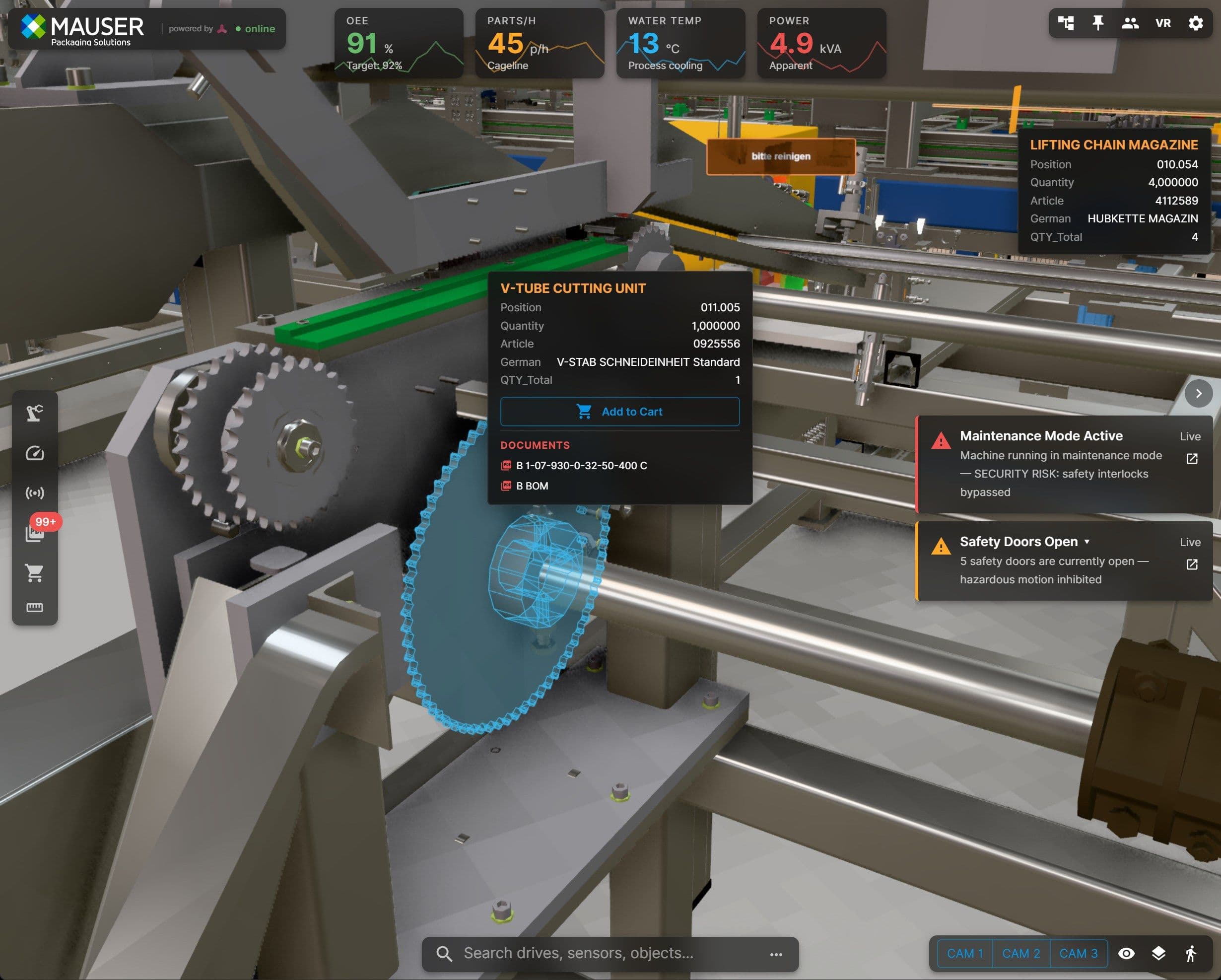
realvirtual web viewer at Mauser: a large industrial machine rendered in the browser, with component metadata and documentation links anchored to the 3D scene. Image courtesy of Realvirtual.io
The technical components for this kind of integration are available today: WebSocket streams for live signals, REST or OPC UA for MES context, structured digital documentation tied to component identifiers, and a 3D viewer (Unity native, WebGL, or a browser-based stack such as the realvirtual.io web viewer, with a public demo at web.realvirtual.io/demo) that renders the combined view. The remaining work for integrators is largely architectural rather than technological.
“We are building our MIS on realvirtual.io. Decision was driven by its architecture: a Unity-based authoring and virtual commissioning environment, self-hosted web runtime, and structured metadata across the machine lifecycle- a combo hard to find. ”

Nils Maier - NILS MAIER / MAUSER PACKAGING SOLUTIONS
Head of Sales & Service MMT
5. Architectural patterns for integrators
Best practices for building a machine information system
Treating the 3D scene as the source of geometric and identifiable truth. Component IDs, kinematic structure, and metadata can be stored in the scene file (for example, as extension data in a GLB or in Unity prefab metadata). Other systems then reference these IDs without redefining them. This approach allows a click in the 3D view to resolve consistently to a signal, an MES record, and a manual section. The screenshot below shows this pattern on a real packaging line: the Unity Editor is the authoring environment in which the machine builder imports CAD, defines the kinematic and component hierarchy, configures sensor and drive behaviour, and attaches the structured metadata that travels with each GameObject for the rest of the machine’s life.

Unity Editor with realvirtual.io tooling: the selected GameObject ENG-048754:1 carries a Runtime Metadata component whose fields — ID, position, quantity, article number, multilingual labels — are the same identifiers used at runtime to resolve clicks to live signals, MES context, and documentation sections. Image courtesy Realvirtual.io
In the inspector on the right, the runtime metadata and runtime interactable components are how the spatial-index pattern is implemented in practice: the component ID lives on the GameObject, not in an external mapping table, so the export to GLB carries the identifier with the geometry. Virtual commissioning happens in the same scene — drive and sensor models from the realvirtual core respond to the connected PLC, exercising the kinematics and the signal mapping before the physical machine exists. Once the scene is signed off, the same authored content is exported as the GLB delivered to the runtime, with no separate downstream re-modelling step.
Using thin, purpose-specific adapters for each data layer. A WebSocket adapter for signals, a REST or OPC UA client for MES, a document service exposing manuals and schematics by component ID. Each adapter is responsible for one source. Toolkits such as realvirtual.io structure the signal and scene side along these lines; the same pattern can be extended to MES and documentation.
Versioning the Machine Information System alongside the software. Where documentation is provided digitally, the machinery regulation requires that the EU declaration of conformity and instructions for use remain accessible for the lifetime of the machine, including across software updates. The pragmatic answer is broader than documentation alone: the entire machine information system — the 3D scene, signal mappings, component metadata, structured documentation, and the captured operational knowledge that accumulates over years — is itself a versioned artifact, tied to a specific machine serial number and software release. The properties needed here are the ones software development has already solved over the past two decades: immutable historical states that let any past delivery be reconstructed exactly, signed tags marking the placing-on-the-market state for regulatory purposes, branches for machine variants and customer-specific configurations, and distributed clones that survive any single tool vendor over a ten-year-plus horizon — typically the actual operating life of industrial machinery, not the regulatory minimum. Git, applied at the level of a whole machine package rather than just to source code, fits this set of properties remarkably well. Systems such as Gitea (the archive layer in the realvirtua.io reference architecture in section 6) are turning into a natural delivery and archive format for industrial machine packages, with versioning patterns that have been load-bearing in software development translating directly to the constraints of traditional machinery delivery.
Exposing the documentation set through a structured API. A document service that returns the relevant manual section in response to a component ID and a fault code is useful to a human operator. The same structured access also supports use cases discussed in Part 2, where AI tools can ground their output in the manufacturer’s actual documentation rather than relying solely on training data.
6. A reference architecture
The elements introduced so far — the four data layers, the machine information system concept, and the architectural patterns above — combine into a reference architecture that integrators can adapt. The diagram below shows the realvirtua.iol reference stack — authoring environment, Gitea archive, machine information system runtime, and plant connection — as one concrete instance of the pattern. The same general split between authoring and delivery can be implemented with different specific tools.

The realvirtual.io Authoring-and-Delivery Architecture — one concrete instance of the pattern described in this eBook. Diagram courtesy of realvirtual.io
- On the authoring side, Unity Editor consumes CAD and 3D assets from the Unity Asset Manager and machine metadata from supplier AAS sources (Siemens, Festo, ABB) and the PDM system, producing metadata, signal, and documentation mappings against the realvirtual.io Core. Unity is then used to set up the imported machine CAD model by applying materials, kinematic behavior, and motion constraints to individual components. This transforms the static geometry into a fully interactive and physically realistic 3D machine model that users can navigate and operate in real time.
The export bundle — 3D machine model (GLB), AAS data, documentation, and the signed Declaration of Conformity — is archived in a Gitea repository as a tagged release, intended as the 10-year archive required under Machinery Regulation (EU) 2023/1230.
- On the delivery side, the machine information system runtime — realvirtual.io WEB on Three.js, TypeScript, AGPL-licensed and self-hostable — deploys from the Gitea archive and connects to the running plant via rv Connect (live signals), InfluxDB (time-series), and the machine’s PLC interfaces, presenting machine state, documentation, maintenance, spare-part management, and analysis to the operator.
- The realvirtual.io core — shared drive, sensor, and kinematic behaviour — exists in both the authoring and runtime environments: as a Unity component during authoring and virtual commissioning, and as a Three.js component at runtime, so the same behaviour models that drive simulation also drive the delivered Machine Information System.
- The existing automation system — PLCs, drives, sensors, robots, MES — is unchanged at the bottom of the stack. Above it sits the signal layer and the MES layer that most integrators are already building. Alongside these, the documentation service, structured by component ID and fault code, fulfils both the regulatory archive requirement and the operator’s need for fast, authoritative reference material at the machine.
Click here for part 2, where we discuss how an MCP and agent layer fits onto it without changing the underlying architecture.
Get the e-book
Fill out this form to access cutting-edge insights and solutions from industry experts


