The Reasoning Layer: LLMs, Agents, and MCP
A practical guide for system integrators, OEMs, and automation engineers - part 2
In partnership Thomas Strigl, CEO, realvirtual.io
About the author: Thomas Strigl is CEO of realvirtual.io and has over 18 years of experience in simulation and automation software.
Click here for part 1 of this e-book series, From visualization to action: Unity, machine information systems, AI agents, and the industrial digital twin.
Part 1 of this e-Book series introduced the architectural foundation behind a modern machine information system: the convergence of live machine signals, MES context, structured documentation, and spatial 3D interfaces into a single operational surface. It also explored how the new EU Machinery Regulation and emerging standards such as the asset administration shell (AAS) are pushing machine documentation toward structured, machine-readable formats. These same foundations — component-linked data, versioned documentation, and contextualized machine state — are what make AI agents and large language models usable in industrial environments.
This second and concluding part of this e-Book series, builds on this architecture by examining the “grounding layer”: how AI systems can access reliable operational and documentation context, and how protocols such as MCP fit into the machine information system stack.
The grounding problem
A common first approach to incorporating large language models in industrial contexts is to add a chatbot to an existing system — a website, a support portal, or an HMI. In practice, this approach has limitations.
A language model on its own does not have access to the live state of the machine, the current production order, or the manufacturer’s specific documentation. Without that context, its responses are based on training data, which may be generic, possibly outdated, and unlikely to include the specific machine in question.
This is generally referred to as the grounding problem. For an LLM to produce useful output in an industrial context, it typically needs structured access to three things: the live state of the machine, the relevant enterprise context, and the manufacturer’s documentation.
The four-layer architecture described in Part 1 corresponds reasonably well to this requirement. Signals provide current state. MES provides operational context. Documentation provides authoritative reference material. The 3D scene provides the spatial frame in which all of this can be presented.
MCP as an integration pattern
The model context protocol (MCP) is an open standard that defines how tools and data sources can be exposed to language models in a consistent way. It specifies how a client connects to a server, how the server advertises its capabilities, and how the model invokes them. Although MCP was originally designed for general developer tooling, the pattern translates fairly well to industrial integration, where the underlying problem — providing consistent access to a heterogeneous set of underlying systems — is similar.
Most plants combine PLCs from different vendors, an MES system, a document management platform, and a historian. Without a standard layer, each new client needs to be integrated against each of these systems individually. With MCP, each underlying system can be wrapped once in an MCP server, and exposed through a uniform interface that any compliant client can use.
For an industrial digital twin, three categories of MCP server are particularly relevant:
- A machine state server that exposes live signal values, alarm states, drive positions, and recent history — backed by the existing signal layer (OPC UA, Beckhoff ADS, MQTT, S7, or a WebSocket-based streaming layer).
- An MES server that exposes orders, batches, KPIs, and quality records — backed by REST APIs, message brokers, or direct database queries.
- A documentation server that exposes the structured digital documentation set — operating instructions, schematics, declarations of conformity, software versions, maintenance procedures — searchable and retrievable by component ID, fault code, or natural language.
An LLM connected to these three servers has a basis for grounded responses. A question such as “why did line 3 stop?” can be answered by reading the alarm state, identifying the affected component, retrieving the relevant troubleshooting section from the manual, and presenting the result with the affected component highlighted in the 3D HMI. The output is grounded in actual systems rather than in the model’s training data.
The reference architecture from section 6 described in part 1 of this e-book series carries directly into this layer. The signal, MES, and documentation services described there are wrapped by MCP servers that expose them through a consistent interface. An LLM or agent runtime — running locally, on an edge server, or in a private cloud, depending on the customer’s data policy — connects to these servers. The resulting responses are grounded in current state, current context, and authoritative documentation.
The 3D HMI sits at the top of the stack and serves two consumers: the operator and any AI-based tools. AI tools use it both as a presentation surface (highlighting components relevant to a response) and as a confirmation surface (displaying proposed actions for human review). The HMI is authored in Unity — covering the CAD import, kinematics, signal mapping, and component metadata that the runtime will use — and delivered either as a Unity-native build for desktop, tablet, AR/VR, or industrial PC, or as a browser-based 3D HMI built on Three.js for WebGL deployments. The same Unity-authored scene file, exported to GLB with consistent component IDs, serves both delivery targets.
Unity’s open C# environment supports both hosting inference directly — through Sentis and ONNX, as discussed in the eBook Design, Simulate, Deploy: Why Unity Matters for Industrial Digital Twins — and acting as a frontend to external runtimes. For most integrator projects, separating the agent runtime from the HMI is the simpler approach, with MCP providing the integration boundary.

Diagram: The reasoning layer
Documentation and grounding
There is a notable overlap between the regulatory direction and the technical requirements for grounded LLM output.
Historically, documentation has been a deliverable cost — produced because it is required, and consulted relatively rarely. Under Regulation (EU) 2023/1230, documentation may be delivered digitally, and when it is, it must be structured, online, and lifecycle-maintained for at least 10 years or the machine’s operating life — typically the latter, given that industrial machinery is rarely retired at the regulatory minimum. Once documentation is in this form, it also has properties that make it suitable as grounding material for language models: it is structured, it is identifiable by component or fault code, and it carries manufacturer authority.
An LLM grounded in the manufacturer’s actual delivered documentation is less likely to produce inaccurate procedures or invented part numbers, because its responses can be traced to specific documentation sections. This may also be relevant for auditability and for integration with the logging and decision-recording obligations the regulation introduces for safety-relevant software.
For integrators, the practical observation is that the work of preparing structured digital documentation — which will be required regardless — also produces an artifact that can be used for grounding LLM-based tools. The two efforts overlap rather than competing for separate budgets.
LLMs as development accelerators
Reducing the cost of integration work
The discussion so far has treated LLMs as consumers of digital twin data — tools that read live state, query documentation, and respond to operators. There is a second role with more direct consequences for integrator economics: LLMs as accelerators in the development of the twin itself.
Building an integrated digital twin involves a significant amount of work that is technically straightforward but time-consuming. Adapter code between the signal layer and the 3D scene. REST or OPC UA clients for the MES. Mapping tables between PLC variables and component IDs. Project-specific charts, dashboards, and small UI components in the HMI. Schema work to align documentation sections with components in the scene. None of these tasks are particularly difficult; they are manual, repetitive, and project-specific.
LLM-assisted coding tools can reduce the effort required for this kind of work — generating adapters for a new MES API, scaffolding chart components, drafting mappings between signal tables and kinematic hierarchies. The effect is not that integrators stop writing code, but that the routine integration work takes less time. This matters in industrial contexts because the long tail of small, project-specific glue code has historically been one of the main reasons integration projects are expensive.
Why standardised interfaces matter
This effect compounds when the underlying interfaces are standardised. MCP servers exposing machine state, MES data, and documentation are easier targets for LLM-assisted development than ad-hoc bespoke APIs. The combination of standardised interfaces and LLM-assisted development lowers the threshold for building integrated digital twins.
The limits of LLM-generated code
Two limitations are worth noting. LLM-generated code is a draft, not a deliverable; for safety-relevant or control-system code, the same review and validation processes apply as for any other code. And the acceleration applies primarily to integration and visualization work, not to underlying control logic, which remains the responsibility of automation engineers using established tools.
Separating authoring from runtime delivery
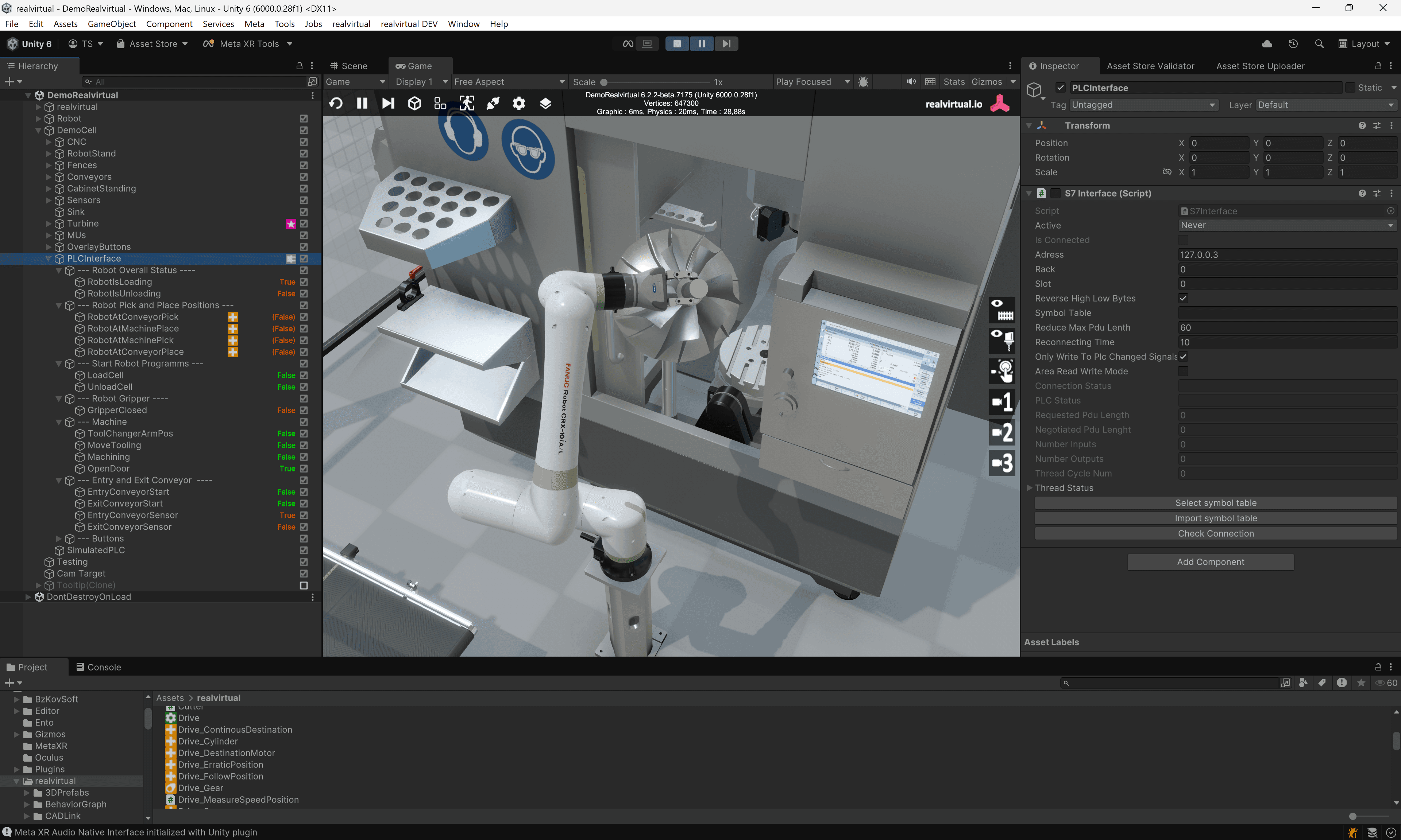
A useful architectural pattern in this context is to separate the authoring environment from the delivered artefact. The authoring environment is Unity — the established platform for industrial digital twins, used as the editor where the machine builder imports CAD, defines kinematics, configures behaviour models, and links documentation to components. Unity provides the depth of tooling, the CAD import pipeline, the kinematic and physics support, and the multi-platform build targets that industrial projects need. The delivered artefact, however, runs in the customer’s environment for the lifetime of the machine and benefits from being open and self-hostable: a browser-based viewer built on standard web technology (Three.js, TypeScript) consuming a standard scene format (GLB). The realvirtual.io web viewer, with its Unity-based authoring stack feeding an AGPL-licensed open-source web runtime, is one example of this pattern in production today.

Image courtesy realvirtual.io
The broader implication for Industry 4.0
Taken together, these effects have a broader implication for Industry 4.0. A common obstacle to integration projects has been the cost of stitching heterogeneous systems together. As that cost falls, the digital twin becomes more attractive as an integration platform — not just a visualization product, but the layer where signals, enterprise data, documentation, and visualization converge. For system integrators, this is the more durable role of the digital twin: less a deliverable in itself, and more the place where everything else meets.
Agents on the shop floor — A spectrum
The term “agent” covers a range of behaviors with quite different risk profiles. It is useful to be specific about which is meant.
- At the most constrained end are read-only diagnostic tools. They observe state, read documentation, and answer questions. They do not write to control systems. An operator asks why a line stopped; the system reads the alarm state, looks up the code in the manual, and explains. This is a reasonable starting point and, for a number of use cases, also a reasonable ending point.
- In the middle are advisory tools. They observe state and propose actions — a setpoint change, a maintenance task, a parameter adjustment — but do not execute them. The operator confirms or rejects each proposal. The 3D HMI can serve as the confirmation surface, displaying the affected component and the proposed change in spatial context before any write occurs. This pattern preserves human judgment in the decision loop while still using AI assistance for diagnosis.
- At the least constrained end are action-taking systems that write to PLCs, change recipes, or dispatch orders without per-action human approval. This is technically feasible in some contexts, but introduces additional considerations under the new machinery regulation. Cybersecurity is now an essential health and safety requirement under Annex III, and AI-based safety functions are explicitly within scope of the regulation's high-risk machinery list, requiring stricter conformity assessment. Any path that allows an LLM-driven system to write to a control system is also a potential attack path. Such systems generally need to be designed with the same care as any other control system component with write access, including the logging and data-recording obligations the regulation introduces for safety-relevant software.
A common posture for early projects is to default to read-only, expand to advisory with explicit operator confirmation, and treat any action-taking capability as a control system component subject to the same review and validation as PLC code.
A practical starting point for integrators
For integrators considering where to begin, an incremental approach tends to work better than an ambitious one.
A practical first implementation could include:
- Using an existing machine project: Start with a machine that already has a 3D HMI and a structured documentation package being prepared under Regulation (EU) 2023/1230.
- Exposing documentation through an MCP server: Wrap the documentation set in a single MCP server that supports retrieval by component ID.
- Connecting the 3D HMI to documentation services: Configure the existing 3D HMI so that selecting a component retrieves the relevant manual section automatically.
- Adding a grounded AI interface: Introduce a chat panel alongside the 3D view using a general-purpose LLM grounded against the documentation MCP server.
Expected outcomes
The result is a machine where an operator can ask a question, receive an answer that cites the manufacturer’s documentation, and see the relevant component highlighted in the 3D view. There are no control states, no autonomous actions, and no new automation infrastructure. The benefits — reduced support calls, improved first-time fix rates, easier access to manufacturer knowledge — are measurable and the risks are limited.
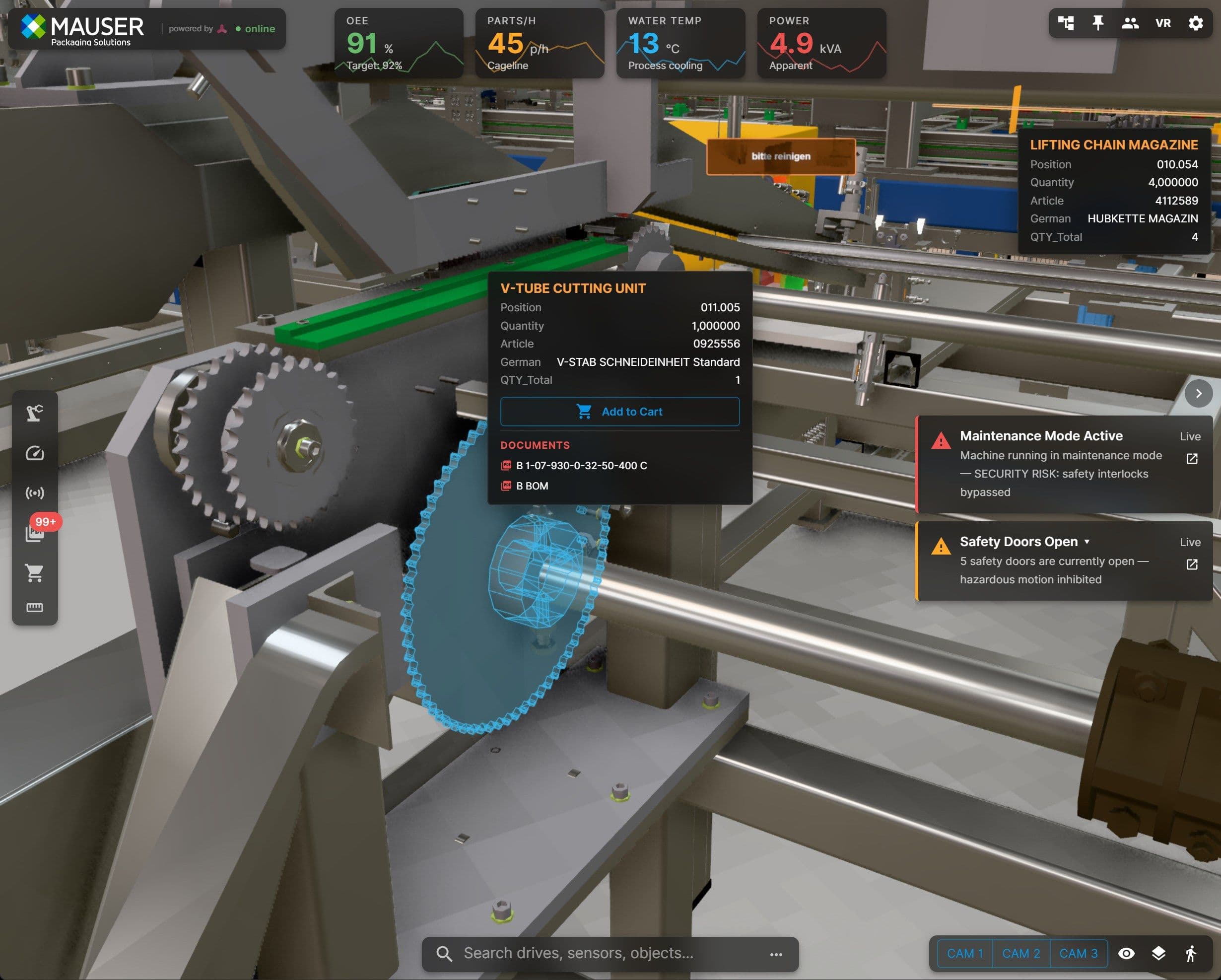
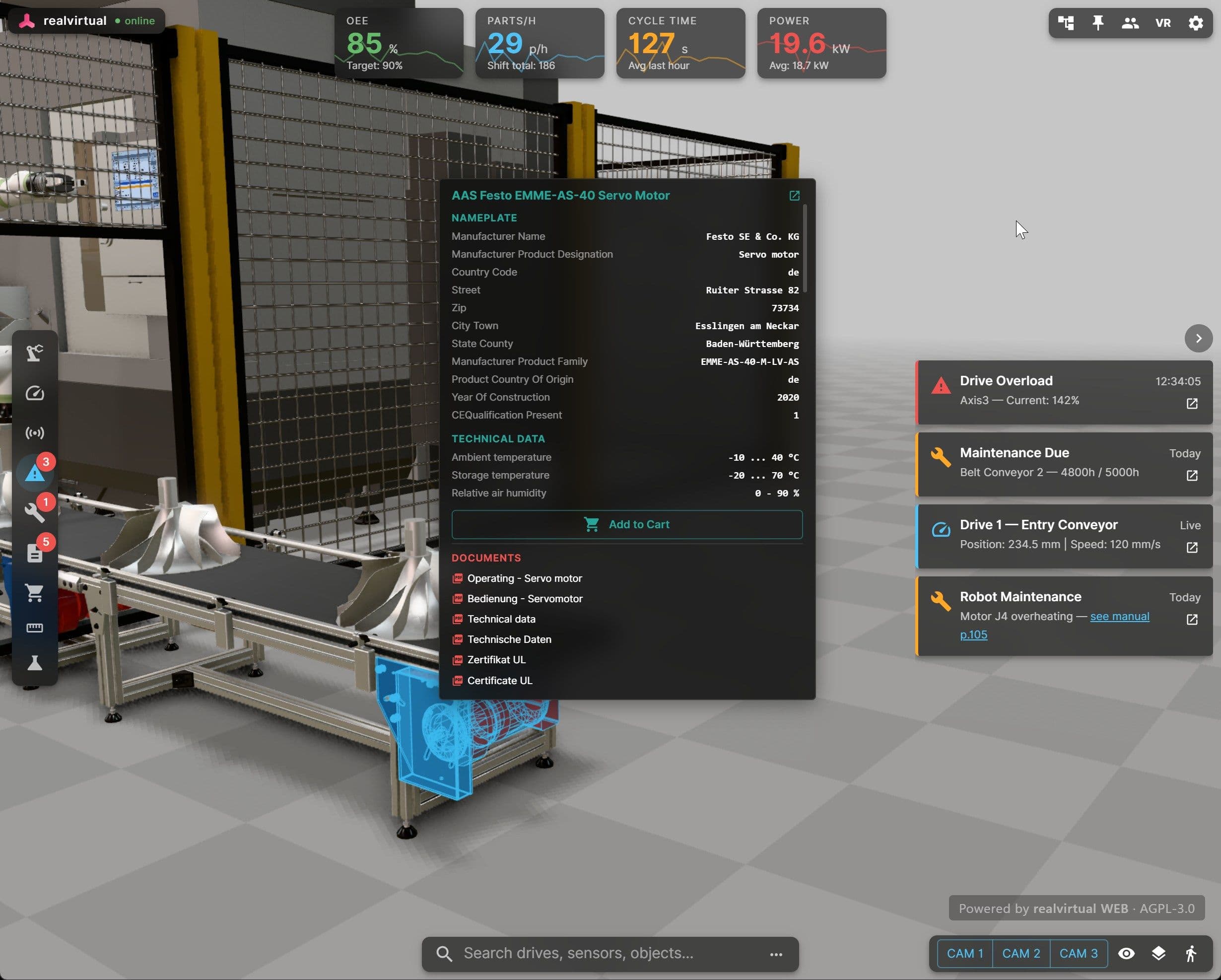
For integrators who want to see what such a system can look like in practice, a public demonstration of a browser-based 3D HMI consuming live signal data is available at web.realvirtual.io/demo. The underlying architecture — Unity as the authoring environment, an open web stack for delivery, and a standard version control system such as Gitea for storing the delivered package across the regulatory ten-year horizon — is a pattern integrators can adopt and adapt to their own projects.

Public demo of the realvirtual Web Viewer at web.realvirtual.io/demo, running in the browser. Image courtesy Realvirtual.io
From this starting point, further steps can be added incrementally. A signal-layer MCP server allows questions about live state. An MES connection enables questions about current orders. Advisory recommendations with operator confirmation in the 3D HMI extend the system further without changing its fundamental risk profile. Each step is testable and reversible on its own.

Image courtesy of realvirtual.io
The architecture that supports both compliance and AI
The previous eBook closed with the observation that digital twins are an organizational investment as much as a technical one — that virtual commissioning, for example, only delivers value when the surrounding processes are willing to change. A similar observation applies here.
Two timelines are now converging on integrators. The machinery regulation has been known since 2023, but the practical work of preparing for the 20 January 2027 application date — new cybersecurity provisions that are mandatory, and the now-explicit option of structured digital documentation with lifecycle maintenance — is moving from planning into execution. In parallel, AI tools are creating a demand for structured, grounded data. These can be addressed as separate projects, but the underlying work overlaps significantly. The four-layer architecture described in Part 1 supports both the operator and any AI tools added later. Structured digital documentation prepared for regulatory compliance is also useful as grounding material. The 3D HMI can serve as a unified surface for all of these.
The operational benefits described in Part 1 — faster diagnosis, lower expertise thresholds, contextualised information delivery, meaningful remote support — apply regardless of regulatory context. Integrators outside the EU, or working on systems not covered by the machinery regulation, gain the same operational advantages from the same architecture, without the regulatory deadline as a forcing function. The architecture stands on its operational case alone; the regulation simply makes the timing explicit for the European market.
Autonomous operation is not the appropriate first deliverable. A more realistic starting point is a machine that an operator can query, that an integrator can support, and that a manufacturer can keep current for the regulatory ten-year horizon. The tools and standards needed to build such a machine are already available, and most of the foundation is work that integrators are required to do regardless.
Get the e-book
Fill out this form to access cutting-edge insights and solutions from industry experts
More from Unity